Show Posts

This section allows you to view all posts made by this member. Note that you can only see posts made in areas you currently have access to.


Messages - Theo

Pages: [1]
1
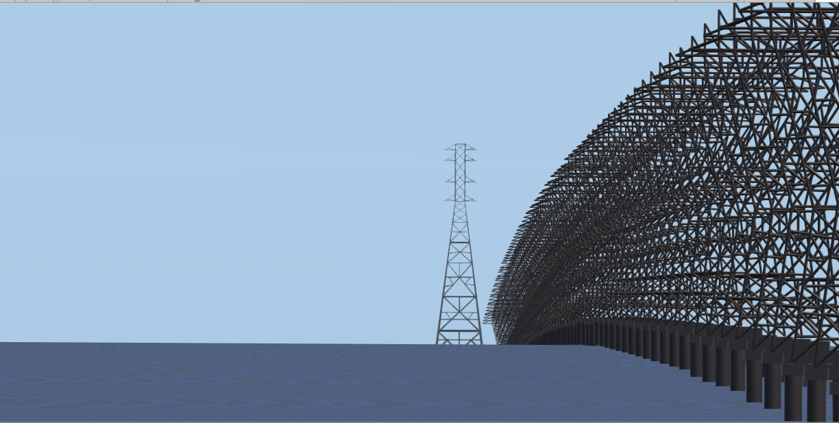
Videos from a flat earther posted today of the causeway:


Appears to me that Soundly's observations are confirmed.  Visible curvature and the end of the causeway disappears behind the horizon while the top of the buildings of New Orleans are still visible.

Compliments to Jose Gonzalez for actually doing some research! 

2
Then why do the concrete structures supporting the towers disappear at the horizon while the thinner towers can still be resolved much farther in the distance?  Why the apparent curve in the powerline towers?  More lens distortion?
Your question should be: "Why is there MORE CURVATURE BEING REPRESENTED IN THIS IMAGE DEPICTING TEN MILES STRAIGHT AWAY FROM THE POV THAN THERE IS DEPICTED IN AN IMAGE SUPPOSEDLY TAKEN AT THE ALTITUDE OF A CONCORD!?!?"

When you can answer that question AND provide an actual photograph of the curvature you got something...

Until then, nothing but chirps so far from you and all of the other expurttz...

LOL!
Nobody has claimed here that you can see the curve perpendicular to your line of sight from the ground.  Your field of view is too small and the curve too slight. You are only looking at a few miles.
However in the image I posted you are looking at 15 miles in your field of view along your line of site so the curve is obvious unless you're in denial.  Would you like me to demonstrate the curve of the towers by superimposing some straight lines on the image?
Fifteen miles?

Do not bother with superimposed images of lines on the image...

You would probably only be hacking those images from NAZA (who you probably are) or making up some other fictional story to go along with the rest of the BS...


What in the world does Nasa have to do with Lake Pontchartrain other than to serve as a diversion to avoid backing up your claim that "lens distortion" is responsible for the curve in the Concord picture?

I do understand why you don't want to see any straight lines on the power line picture, I wouldn't either had I claimed that they don't curve, but here is a "hacked" image for you none the less...

https://i.imgur.com/ycIXUUD.jpg


Now would you kindly support your claim about lens distortion with evidence instead of avoidance and obfuscation?

What type of camera lens is responsible for causing a curve in the horizon in the center of the image while leaving the  Concord  with no distortions?

How does a very slight curve in the vertical axis of a window cause the horizon to curve and how is it that it only happens when at altitudes where the curvature of earth becomes visible?


3
Been debunked before.

A guy was hoaxing those curved earth shots ...


Here are some of the layers used to make these hoaxes.


This guy 'Soundly' hoaxes shots and adds them to the internet.

Here he is asking for help from his friends.


And below is another of his terrible hoaxes ... I think he imagines we live on Kerbal.


Any of the images from 'Soundly' have to be instantly dismissed. It is fakery.
https://flatearthinsanity.blogspot.com/2017/06/soundly-shows-flat-earthers-curve.html

Are you  the guy who claimed that the power line didn't exist then fled the thread when proven wrong?

So now you claim fake?

Well sir the making of video was lived streamed to prevent flat earthers claiming fake and the "layers" you posted were made AFTER the video to model the power lines.
I challenge you to find that image posted somewhere BEFORE Soundly's video.

Funny that you missed this image:

https://i.imgur.com/rTTvBW9.jpg


That is a model of the power line if the earth were flat.  Definitely not what is observed.
A comparison :

https://i.imgur.com/XTseJVU.png


For those interested you can view a model of the power line on a flat earth or reality here...

http://walter.bislins.ch/bloge/index.asp?page=Comparison+of+Globe+and+Flat-Earth+Model+Predictions+with+Reality#H_Lake_Ponchartrain_Transmission_Line


4
Please provide an example of this type of camera lens or a diagram of how it works, I really would like to purchase one.
Deal!

Once you have posted a picture of curvature of the surface of the Earth I will get right back with you!

How about one that you go and observe first hand?

https://i.imgur.com/Bir01ql.jpg


Now, where can I find a lens that causes horizons to curve in the center of an image and yet leaves the edges distortion free?  An online summary or description will be fine, I'll do the shopping once I know what to look for.  Thanks in advance.
Please...

That image presents no curvature...

Hey CuriousSquirrel!!!

You gonna correct this guy or what!?!?!

LMAO!!!

Then why do the concrete structures supporting the towers disappear at the horizon while the thinner towers can still be resolved much farther in the distance?  Why the apparent curve in the powerline towers?  More lens distortion?

Nobody has claimed here that you can see the curve perpendicular to your line of sight from the ground.  Your field of view is too small and the curve too slight. You are only looking at a few miles.
However in the image I posted you are looking at 15 miles in your field of view along your line of site so the curve is obvious unless you're in denial.  Would you like me to demonstrate the curve of the towers by superimposing some straight lines on the image?

I'll be happy to oblige when you tell me the type of camera lens you claim causes the distortion in the Concord image. 

Back to the OP,  I'd be interested to know how the Concord windows can cause a curvature in the horizon when they curve only along the vertical axis to match the fuselage.    Wouldn't the curve have to be along horizontal axis?

Have any diagrams on how the windows act as a lens and cause the apparent curvature in the horizon?

5
Please provide an example of this type of camera lens or a diagram of how it works, I really would like to purchase one.
Deal!

Once you have posted a picture of curvature of the surface of the Earth I will get right back with you!

How about one that you go and observe first hand?

https://i.imgur.com/Bir01ql.jpg


Now, where can I find a lens that causes horizons to curve in the center of an image and yet leaves the edges distortion free?  An online summary or description will be fine, I'll do the shopping once I know what to look for.  Thanks in advance.

6
You can claim "no distortion" as much as you like...

The facts have been, are, and will forevermore be, this:

If you are looking at something with a piece of glass placed in between you and the something being observed your vision is being distorted by the piece of glass.

Plain, pure, and simple.

Drops mic...

End of topic.

What is causing the curvature in this picture and why does it distort the horizon into a curve and not the Concord itself?

https://i.imgur.com/Nmvvw9b.jpg


I've never heard of glass with such selective properties and would love to see other examples.
First, I believe we are writing about the surface of the Earth, not the tops of clouds.

But let us simply state your pretty picture is altogether a 100 percent complete and accurate rendering. If that is case, then you can further state we live on a ball much less than the stated figure...

So take your picture back and come back when you have something not distorted much like this one, also presented in support of the ball earth myth:


The camera causes your distorted picture.

As for your claim to have never heard of glass causing distortion?

That is just pure bupkus and I am surprised you would resort to such tactics here. /sarcasm

Your image shows so much distortion on the edges that even the small camera body is curved!

The image I provided has the horizon in the center where ALL lenses have the least distortion and the Concord below center where barrel effects, if any, should show up.  Yet the Concord is not distorted.

Are you actually claiming that this image was taken with a camera lens that distorts the center of an image and yet leaves the edges not distorted?

Is this magic lens altitude sensitive like Concord windows and only distorts at altitudes where curvature is apparent to the naked eye or does it also work the same way on ground?

Please provide an example of this type of camera lens or a diagram of how it works, I really would like to purchase one.

7
You can claim "no distortion" as much as you like...

The facts have been, are, and will forevermore be, this:

If you are looking at something with a piece of glass placed in between you and the something being observed your vision is being distorted by the piece of glass.

Plain, pure, and simple.

Drops mic...

End of topic.

What is causing the curvature in this picture and why does it distort the horizon into a curve and not the Concord itself?

https://i.imgur.com/Nmvvw9b.jpg


I've never heard of glass with such selective properties and would love to see other examples.

8
Quote
Ferromagnet is the typical name for a material that is naturally magnetic. This is in contrast to a material that simply becomes magnetic for a short while after contact with a magnet as a nail is wont to do after some time stuck to a ferromagnet. Lead has the opposite effect, where it actually repels the magnetic force of an object. This is called diamagnetism.

Tom, diamagnetism is a residual effect that all materials have. In this respect, I can be considered magnetic, indeed this is how MRI scanners work. However, the problem for the point you make is that diamagnetism is a dynamic not a static effect. In other words you would need an alternating magnetic field NOT a bar magnet (creating a static field) in order to even see this effect.

Incorrect again, Mr. Physics degree. Here is a video of lead being affected by static permanent magnets:


Pencil leads are made of graphite as the video mentions numerous  times.


https://pencils.com/the-unleaded-pencil/

 There is no lead in pencils. Rather, the core is made up of a non-toxic mineral called graphite. The common name “pencil lead” is due to an historic association with the stylus made of lead in ancient Roman times.

9
Flat Earth Theory / Re: The Horizon is Always at Eye Level
« on: May 31, 2018, 02:01:56 AM »
Bobby I don't think you're dealing with a mirage.  Wouldn't you expect the same effect to occur on the lower part of the Island on the left? They are very close to the same height.  I think your are seeing the top of the rock on right due to refraction not mirage. 


https://i.imgur.com/LiP75oe.jpg

Also wouldn't a mirage appear opposite of your example?  The 2 pyramids being mirrored point to point?

My compliments Sir on your efforts and especially the water level apparatus. 

You already proved the shape with the fact that you see more of the Islands as you rise in altitude
 

https://i.imgur.com/Jc7siJy.jpg

I guess this is just icing on the cake?   ;)


10
Flat Earth Theory / Re: The Horizon is Always at Eye Level
« on: May 30, 2018, 10:25:18 PM »
It's pretty obvious to me where the horizon is and even more so if you adjust the contrast...


https://i.imgur.com/AJIY3nD.jpg

That's a pretty sharp separation between water and sky even without adjusting contrast.
It's almost as sharp as between the water and the ship 

11
1. Rowbotham discusses Theodolite Tangent here: http://www.sacred-texts.com/earth/za/za45.htm

6. Bobby personally performed this sort of water experiment himself and can tell you how sensitive and complex this seemingly simple experiment is. He decided to abandon it. Read his thread: https://forum.tfes.org/index.php?topic=9492.0

1. Rowbotham is only useful as an example of how to bamboozle simple folk with mindgames and twisted logic.

6. The water level equpiment is more than accurate enough for purpose.

Bobby's thread chronicles his journey and the issues faced. It is not a simple experiment.

Surveying is not easy. It is incredibly difficult and sensitive.

Surveying is always in error. Always. The device needs to be finely aligned, positioned, and calibrated. Even then, there is still inherent error.

http://whistleralley.com/surveying/theoerror/

Quote
As any surveyor should understand, all measurements are in error. We try to minimize error and calculate reasonable tolerances, but error will always be there. Not occasionally; not frequently; always. In the interest of more accurate measurements, we look for better instruments and better procedures.

The greater the distance you are trying to align your devices with, the greater the potential error. All devices need to be of superior calibration.

...


You forgot this part from the website you quote mined...

Quote
One major design improvement came with the invention of the transiting theodolite. With this innovation, the telescope was able to swing all the way over on the trunnion axis. This in itself did not reduce any of the inherent error in the instrument, but it gave surveyors the means of doing so. When the scope is inverted, the instrument error is still there, but most of the error reverses direction. By taking the mean of an even number of observations, half direct and half inverted, the error is turned against itself and greatly reduced.

And this:

Quote
The theodolite actually has one advantage over most levels. By inverting the telescope, the collimation can be checked from a single setup.

And this:

Quote
A few seconds, or even minutes, of error here makes no appreciable difference in horizontal distances, but it can play all havoc with elevations. Unlike the horizontal angle errors, this one is constant, which is to say, it is not affected by changes in the direction of the sight. That makes it a fairly simple matter to correct the angle without even adjusting the instrument. In fact, electronic instruments typically have an onboard routine that will measure and correct the vertical angle error. Push a few buttons, sight a target in both positions, and have the instrument store the correction. The procedure takes only a couple of minutes, so it can be done at the beginning of each work day.

In other words just like a carpenter will flip his level to insure accuracy surveyors do the same with theodolites. 
There can be errors in surveying, but elevation of the horizon is child's play and any instrument error is turned upon itself.  A theodolite is more than accurate enough to determine that the horizon is ALWAYS below the horizontal tangent.
Even a cheap builder's level is accurate to 1/16"/100'.  A good theodolite will will be accurate to 1mm/Km.
To say that one can't be trusted to measure the dip of the horizon is ludicrous at best.


12
Flat Earth Investigations / Re: Is surveying an accurate science?
« on: May 30, 2018, 03:01:25 AM »
Every country on the planet uses surveyors for borders, property lines, roads, bridges, etc and if you have a property dispute who do you call?  Surveying is an extremely accurate science.

edby,

What you have there is commonly called a dumpy level.  Unlike transiting theodolites dumpy levels don't measure vertical angles directly, they work in conjunction with someone holding a graduated rod.  It will however serve your purpose to see IF there is a drop in the horizon.  My guess is that it was made in early 50s.  Do you have the tripod or is it a table top model.  I don't see any adjustment screws to plumb the vertical axis.

As mentioned above you can't self-check with it so it is VERY important to check if spirit level is exactly parallel to to the telescope. You can see where the instrument is calibrated above the round level.

Considering the scrutiny you'll be under I recommend a simple test for accuracy that will also give you some practice.

Set up 2 poles in a large area 75' apart.  Set up level in line with poles 75' from 1st pole.  Direct a helper to place a mark on the poles exactly on the cross-hairs. Repeat the process at the same distance in the opposite direction.  Don't worry about the height of first set of lines, you want them to be different heights.
The distance between the marks on each pole should be the same, if not you have some error.  Half of the difference between the sets of marks will be the error per 100'.  Use a sharp pencil as any difference will be small.

https://imgur.com/a/IaGH4Yt


Hope this helps and please excuse the primitive illustration.
If you have any questions about the instrument I'll be happy to assist if I can.

Theo

Edit:
I was mistaken about 2nd position, it should be in the center of the 2 poles, not the end!
Sorry about that, it's been a couple of decades since I've dealt with this stuff.

Pages: [1]